Contents:
1.UmSITE
1.1 Mechanical specification
1.2 Software specification
1.3 Hardware Options
2. Installation
2.1 Antennas installation
2.2 Getting started
2.3 Test call
2.4 Log in
2.5 IP and network configuration (optional)
2.6 Base station sensors
1. UmSITE
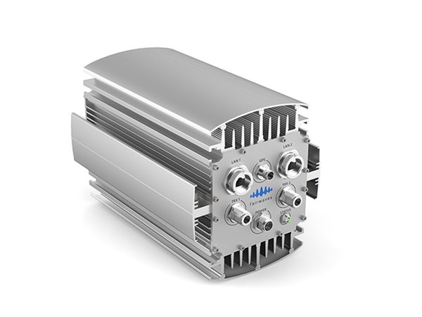
The UmSITE is an IP-backhaul GSM Base Station, seamlessly integrating functionality that is usually provided by GSM components such as BSC, MSC, VLR, HLR and SMSC. Its software-centric design enables unprecedented flexibility, supporting remote configuration, maintenance and upgrade, and covering everything from transmit power control to end user features.
1.1 Mechanical specification
Enclosure
- • Dimensions: 465 x 190 x 170 mm
- • Weight: less than 15 kg
Environmental conditions
- Outdoor
- • -30 C to +45 C operational temperature
RF Input/Output
- • GSM 850/900/1800/1900 band (chosen at order time)
- • 2 independent TRX
- • Diversity receive
- • Multi-ARFCN on each TRX (beta)
- • 10W per channel (2x10W)
- • Real time power control via VTY
Reference Clock
- • GPS (default)
- • OCXO (optional)
CPU
- • Intel Atom
Input Voltage and Power
- • 220 VAC
- • Power consumption: less than 100W
Backhaul Interface
- • RJ45 Ethernet (100/1000Mbit)
Power supply
Fairwaves does not provide the power supply by reason of various places use different power sources. Fairwaves products are compatible with any power sources, including solar panels, as well.
List of the power supplies:
UmSITE-TM10 (100W) ( IP65: Mean Well HLG-100H-30A
UmSITE-TM3 (60~80W) IP65: Mean Well HLG-60H-15A
Indoor power supply: Any basic laptop charger can be used
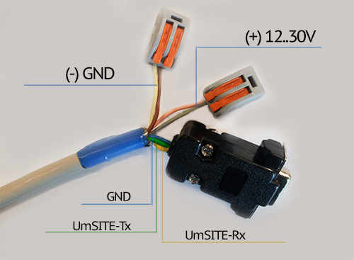
Power/COM-port wires connection schema
Antenna
Fairwaves does not provide GSM antennas. You can use any other antennas suitable for 850/900/1800/1900 GSM frequency band with N-male connectors
1.2 Software specification
Number of Transceivers
- • 2 TRX / 16 timeslots
Supported timeslot configurations
- • CCCH, CCCH+SDCCH/4, SDCCH/8, TCH/F, TCH/H
Voice codecs
- • FR/HR/EFR/AMR; RTP stream
Ciphering
- • A5/0, A5/1, A5/2 and A5/3
GPRS/EDGE
- • GPRS - beta
- • EDGE - planned
Operating System
Embedded Linux
Capacity
- • maximum concurrent calls (Full/Half) Rate 15/30
- • maximum simultaneous SMS 124 (15SDCCH/8 + 1SDCCH/4)
1.3 Hardware options
- • Clocking: OCXO / GPS disciplined
2. Installation
NOTE: Base station comes with already installed and configured software, just attach GPS antenna, GSM antennas and power supply.
Steps:
NOTE: GSM antennas are not included in a standard package. We do not recommend to operating the base station without antennas.
2.1 Antennas installation
Each of the antennas complement each other. The second antenna must have the same position as the first antenna on a mast, as well as the same direction and incline angle to the ground.
For the GPS antenna, there are no strict requirements, only good antenna visibility to the sky
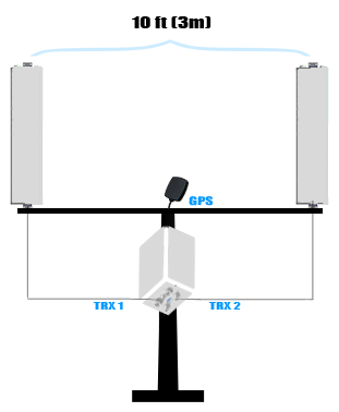
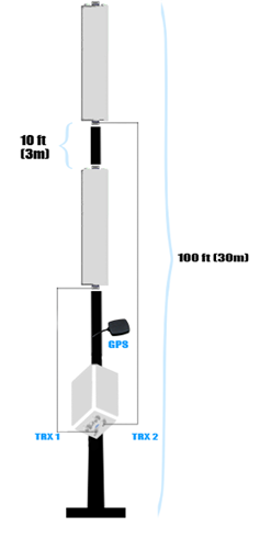
For the mast at least of 100 feet (30m) in height, antennas can be mounted upright within the 10 foot (3m) distance between each other.
NOTE: Every cell is configured with a BCCH carrier. Generally, the TRX ID of BCCH is fixed to be the smallest TRX ID in the cell.
Therefore, TRX1 antenna has to be situated below the TRX2 antenna. For example, if the connection would be established when the TRX1 antenna is higher and then it has been assigned to a timeslot of the lower antenna TRX2, call connection could be lost.
The antenna attached to the TRX1 should not have an advantage by height in that particular case.
2.2 Getting started
-
• Connect to the power source and turn it on. LED on the front panel will begin flashing in one to two minutes after being turned on.
-
• Make sure that the Ethernet cable is connected.
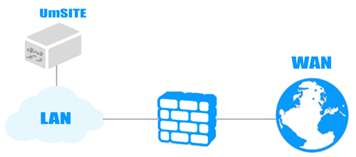
NOTE: We strongly recommend not putting UmSITE on a public network. Connect it to your local network where there is access to the Internet through NAT or Firewall. Keep UDP port 1195 open on your server for Fairwaves VPN in case of technical support
Take any GSM phone with any SIM card and try to search the network. The network might have a different name, such as Fairwaves, 1011, Test, etc.
2.3 Test call
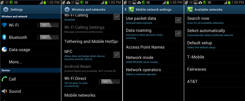
Searching for the Network
-
Launch the Settings from the menu system.
-
1. Select More
-
2. Select Mobile networks
-
3. Select Network operators
-
4. Select Search networks
Options:
-
• 1002 - echo call (listen yourself)
-
• *#100# - to figure out the number that was assigned to your phone.
2.4 Log in
In order to configure UmSITE, you have to login into device remotely over SSH. The Interface configured to obtain IP address via DHCP and also has a static 192.168.50.100
Connect laptop to the UmSITE via Ethernet cable.
NOTE: Make sure your interface in the same subnet as the UmSITE and has IP like 192.168.50.101
- 1. Run PuTTY
- 2. Type IP address: 192.168.50.100
- Login: fairwaves
- Password: fairwaves
You may use a defferent client software for remote access, but we recommend PuTTY (you can download it at www.putty.org ). PuTTY is an open source SSH and telnet client, for the Windows platform.
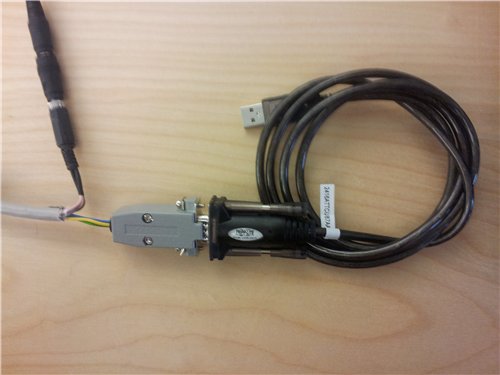
Login over Serial cable (Only for UmSITE)
Serial connection allows you to choose boot options and log into the system if network connection is not available.
You'll get options like:
- 1. Advanced options for Ubuntu
- 2. Test RAM memory
First of all, you have to use USB Serial Adapter for the connection (which is not included in a standard UmSITE package).
For the Windows user putty
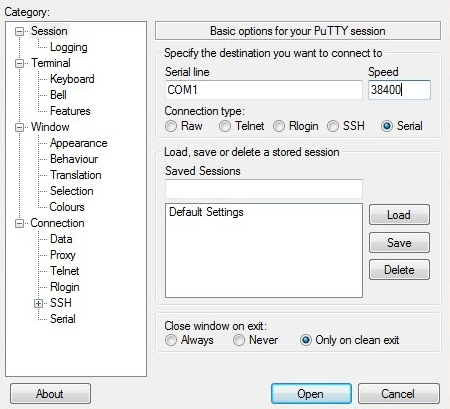
You can find a number of the COM port at the Desktop manager.
For the Linux user minicom
shell> minicom -D/dev/ttyUSB0 -b38400 -o
2.5 IP and network configuration
eth0 - 192.168.10.10 This is internal interface linked to the UmTRX. Do not edit this
eth1 - Configured to obtain IP address through DHCP. In case of recovery, it also has a static IP 192.168.50.100
Edit eth1 in /etc/network/interfaces.d/ In order to change network configuration
Shell> sudo nano /etc/network/interfaces.d/eth1
Refer to Ubuntu documentation for details
NOTE: The base station is configured to get an IP address through DHCP. We also recommend to keeping the configuration for the eth1:1 (192.168.50.50/24) because it's used to as a backup IP address. If you want to configure a static IP address, change eth1 configuration.
2.6 Base station sensors
In order to obtain insights of temperature, voltage and TRX power of the base station you can run:
Shell> umtrx_query_sensors The output is:
Shell> Sensors:
            TempA = 34.312500 C
            TempB = 35.187500 C
       VoltagePR1 =  2.580000 V
       VoltagePF1 =  3.280000 V
       VoltagePR2 =  0.760000 V
       VoltagePF2 =  0.000000 V
      Voltagezero =  0.000000 V
       VoltageVin = 23.620000 V
     VoltageVinPA = 23.640000 V
     VoltageDCOUT = 21.640000 V
TRX 1 power detector:
              VPF =   3.26  V
               PF =  65.2   dBm
              VPR =   2.58  V
               PR =  51.6   dBm
             VSWR =   1.53
            Gamma =   0.209
      Return Loss =  13.6   dB
    Mismatch Loss =   0.194 dB
    Through power =  95.63  %
  Reflected power =   4.37  %
TRX 2 power detector:
              VPF =   0.00  V
               PF =   0.0   dBm
              VPR =   0.76  V
               PR =  15.2   dBm
             VSWR =    nan
            Gamma =   5.754
      Return Loss = -15.2   dB
    Mismatch Loss =     nan dB
    Through power =    nan  %
  Reflected power =    nan  %
NOTE: If 'Return Loss' value:
< 6dB = major alarm state (100% malfunction)
< 10db = minor alarm state (Check antenna for water subject)
> 10dB = partly good (probably bad antenna or water in cable/connector)
> 12dB = good
> 15dB = excellent