Software configuration manual
Contents:
1.Introduction
1.1 GSM network architecture
1.2 Fairwaves network architecture
2. Configuration
2.1 Log in
2.2 IP and Network configuration
2.3 GSM parameters
2.4 Runtime Logs
2.5 Multi BTS configuration
2.6 Handover
3. FreeSWITCH Configuration
3.1 Setiing up a new gateway
3.2 FreeSWITCH Traces
3.3 Codecs
4. Subscribers properties
4.1 Virtual Teletype. Login. Privileged mode
4.2 Add Subscriber
4.3 Changing the subscriber phone number
4.4 Changing the subscriber name
4.5 Changing the authorization status
4.6 Changing subscriber properties
5. Configuration via VTY
5.1 Log in
5.2 Privileged Node
5.3 Configuration Node
5.4 Network Configuration
5.5 BTS Configuration
5.6 TRX Configuration
5.7 SMPP Configuration
6. Spectrum License Required
Glossary
SDR
Software Define Radio
BSC
Base Station Controller
BTS
Base Transceiver Station
ARFCN
Absolute Radio Frequency Channel Number
DHCP
Dynamic Host Configuration Protocol, IETF RFC 2131
IP
Internet Protocol, IETF RFC 791
MS
Mobile Station
MSC
Mobile Switching Center
NITB
Network In The Box
OML
Organization and Maintenance Link, 3GPP TS 12.21
RSL
Radio Signalling Link, 3GPP TS 08.58
SSH
Secure Shell, IETF RFC 4250 to 4254
VTY
Virtual Teletype
ISDN
Integrated Services Digital Network
PSTN
Public Switched Telephone Network
1. Introduction
This manual should help you get started with Fairwaves software. It covers all aspects of configuring and running the Fairwaves products, such as UmSITE and UmDESK.
1.1 GSM Network Architecture
A GSM network is made up of multiple components and interfaces that facilitate sending and receiving of signaling and traffic messages. It is a collection of transceivers, controllers, switches, routers, and registers. The GSM network can be divided into the following parts.
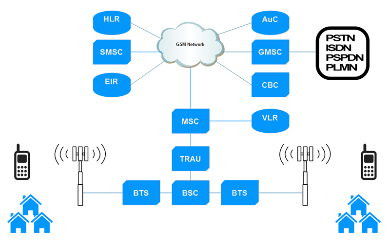
Mobile Station (MS)
is made up of two components:
1. Mobile Equipment (ME) refers to the physical phone itself.
-
2. Subscriber Identity Module (SIM) is a small smart card that carries information specific to the subscriber, such as IMSI, TMSI, Ki (used for encryption), Service Provider Name (SPN), and Local Area Identity (LAI).
Base Station Subsystem (BSS)
consists of two elements:
-
1. Base Transceiver Station (BTS) is responsible for carrying out radio communications between the network and the MS. It handles speech encoding, encryption, multiplexing (TDMA), and modulation/demodulation of the radio signals.
-
2. Base Station Controller (BSC) handles allocation of radio channels, frequency administration, power and signal measurements from the MS, and handovers from one BTS to another.
Network Switching Subsystem (NSS)
provides the main control and interfacing for the whole mobile network.
-
1. Mobile Switching Centre (MSC) is the main element delivery node for GSM, responsible for the routing voice calls and SMS. MSC acts like a normal switching node within a PSTN or ISDN, but also provides additional functionality to enable the requirements of a mobile user to be supported. These include registration, authentication, call location, inter-MSC handovers and call routing to a mobile subscriber. It also provides an interface to the PSTN so that calls can be routed from the mobile network to a phone connected to a landline. Interfaces to other MSCs are provided to enable calls on different networks.
-
2. Home Location Register (HLR) is a central database that contains details of each mobile phone subscriber that is authorized (AuC) to use the GSM core network.The HLR maintains information such as the MSISDN, IMSI, current location of the MS, roaming restrictions, and subscriber features.
-
3. Visitor Location Register (VLR) contains a subset of the information about the mobile subscribers which came from the other MSC.
-
4. Equipment Identity Register (EIR) is a database that keeps tracks of handsets on the network using the IMEI.
-
5. Authentication Centre (AuC) is responsible for generating the necessary cryptovariables for authentication and encryption on the network. The AuC also stores the Ki for each IMSI on the network. Although it is not required, the AuC is normally physically collocated with the HLR.
-
6. Gateway Mobile Switching Centre (GMSC) is a gateway between two networks. If a mobile subscriber wants to place a call to a regular land line, then the call would have to go through a GMSC in order to switch to the Public Switched Telephone Network (PSTN).
Operation Support Subsystem (OSS)
is used to control and monitor the overall GSM network and it is also used to control the traffic load of the BSS. You can get more information about specification, protocol stack, security, etc. here.
1.2 Fairwaves network architecture
The Fairwaves Architecture defines a set of components, protocols, services and configurations used to build cost-optimized mobile networks in rural and remote areas.
In contrast to the traditional GSM architecture that is highly centralized, dependent upon backhaul and making heavy use of this, the Fairwaves Architecture is built upon a distributed VoIP core that benefits from local switching and is resilient to network failure.
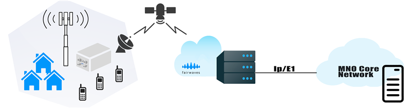
All the functions of a mobile network are integrated into a single, self-contained cellular base station, that is built to withstand the elements and suited to being powered from off-grid energy sources such as solar.
Scaling and integration with operator networks is made possible via local and cloud-based UmCORE servers.
The Fairwaves Architecture significantly reduces the financial and technical barriers to deploying cellular networks, while ensuring that during their operation backhaul costs are minimised thanks to local call routing and use of effective voice compression algorithms.
For more details: fairwaves.co and umtrx.orgThis software is licensed under GNU Affero General Public License Version 3. Refer to osmocom for details.
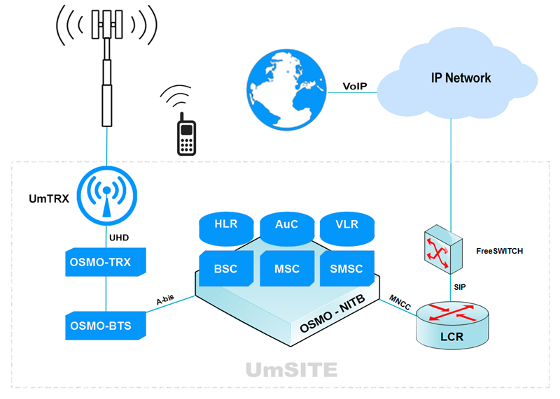
The UmSITE is more than simply a rugged BTS and is essentially a complete network-in-a-box, seamlessly integrating functionality that is usually provided by GSM components such as BSC, MSC, VLR, HLR and SMSC. Its software-centric design enables unprecedented flexibility, supporting remote configuration, maintenance and upgrade, and covering everything from transmit power control to end user features.
Independent Base stations (UmSITE) can be clustered through a distributed HLR connected via peer to peer links
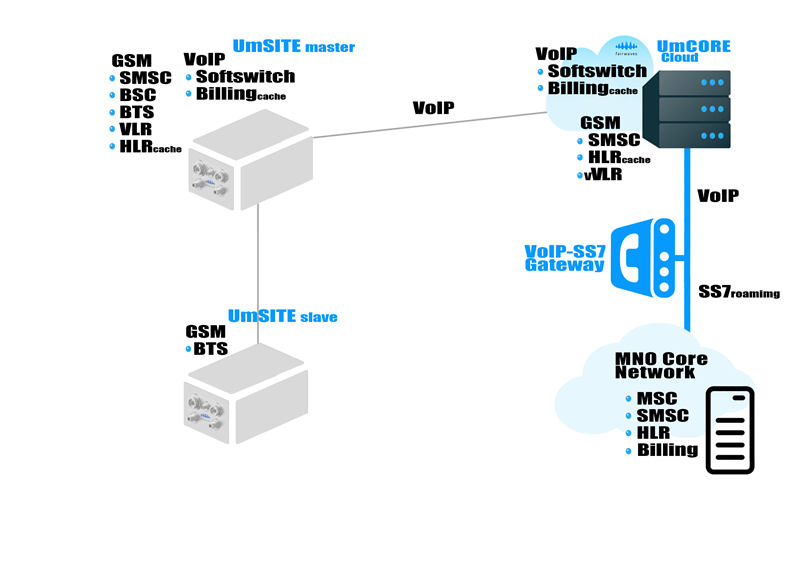
Core Network
The UmCORE technology provides synchronization across distributed UmSITE installations, and enables integration with existing networks via VoIP and SS7.
Features include:
- 1. System management console
- 2. Dynamic network information
- 3. Event logging
- 4. Billing
- 5. HLR
UmCORE is available in customer co-located and cloud versions.
UmCORE LocalUmCORE Local is a turnkey solution comprised of a compact low power server loaded with preconfigured software, designed for ease of deployment and customer co-location.
UmCORE Local can be managed and upgraded remotely via a secure VPN link.
UmCORE CloudUmCORE Cloud is a hosted solution that provides an additional layer of resilience and is used to enable integration with existing operator networks via a VoIP-SS7 gateway.
2. Configuration
2.1 Log in
NOTE: to detect radio devices and confirm connectivity run:
uhd_find_devices
or
uhd_usrp_probe
In order to configure UmSITE, you have to login into device remotely over SSH. Interface configured to obtain IP address via DHCP and also has a static 192.168.50.100
Connect laptop to the UmDESK/UmSITE via Ethernet cable.
NOTE: Make sure your interface in the same subnet as the UmSITE/UmDESK and IP like 192.168.50.101
- 1. Run PuTTY
- 2. Type IP address: 192.168.50.100
- Login: fairwaves
- Password: fairwaves
Once you logged in, you will get access to Linux terminal.
You may use a deferent client software for remote access, we recommend PuTTY (you can download it at www.putty.org ). PuTTY is an open source SSH and telnet client, for the Windows platform.
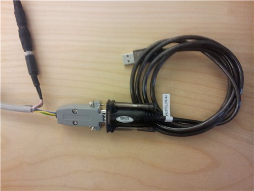
Login over Serial cable (Only for UmSITE)
Serial connection allows you to choose boot options and log into the system if network connection is not available.
You'll get options like:
- 1. Advanced options for Ubuntu
- 2. Test RAM memory
First of all, you have to use USB Serial Adapter for the connection (which is not included in a standard UmSITE package).
For the Windows user putty
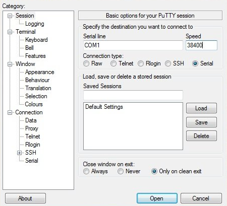
You can find a number of the COM port at the Desktop manager.
For the Linux user minicom
Run this command to connect via serial cable:
shell> minicom -D/dev/ttyUSB0 -b38400 -o
2.2 IP and network configuration
eth0 - 192.168.10.10 This is internal interface linked to the UmTRX. Do not edit this
eth1 - Configured to obtain IP address through DHCP. In case of recovery, it also has a static IP 192.168.50.100
Edit eth1 in /etc/network/interfaces.d/ In order to change network configuration
Shell> sudo nano /etc/network/interfaces.d/eth1
Refer to Ubuntu documentation for details
NOTE: Base station configured to get IP address through DHCP. We also recommend keeping the configuration for the eth1:1 (192.168.50.50/24), because it's used to as a backup IP address. If you want to configure a static IP address, edit eth1 configuration.
2.3 GSM parameters
GSM network configuration parameters are stored at openbsc.cfg You can use interactive VTY telnet interface for configuration editing, and it is also possible to make changes directly in the configuration file.
in order to edit openbsc.cfg run:
Shell> sudo nano /etc/osmocom/openbsc.cfg
Network level:
mobile network code
- unique identification number of mobile phone network
network country code
- unique identification number of mobile phone operator
short name
- short name of the network
long name
- long name of the network
auth policy
policy of access to the network. it's open for all by default. Possible values are:
- closed: Don't allow anyone who is not marked as authorized=1 in the HLR database
- accept-all: Accept everyone into the network
- token: Use a special TokenAuthPolicy
location updating reject cause <2-111>
- Set the CAUSE value when sending LOCATION UPDATING REJECT to a MS. Possible values are defined in GSM TS 04.08 / 10.5.3.6.
encryption a5 (0|1|2)
- Enable/Disable A5/X encryption on the network.
mm info (0|1)
- Should we send MM INFO messages with network name and timezone information?
handover (0|1)
- Enable BSC in-call handover between multiple BTS
handover window rxlev averaging <1-10>
- Over how many SACCH frames should the Rx Level of the serving cell be averaged?
handover window rxqual averaging <1-10>
- Over how many SACCH frames should the Rx Quality of the serving cell be averaged?
handover window rxlev neighbor averaging <1-10>
- Over how many SACCH frames should the Rx Level of a neighbor cell be averaged?
handover power budget interval <1-99>
- Every how many SACCH frames should the BSC think about performing a power budget (rx level) handover?
handover power budget hysteresis <0-999>
- How large should the hysteresis be, i.e. to prevent continuous handover back and forth
handover maximum distance <0-9999>
- What is the maximum distance from a BTS, after which we try to perform distance handover?
timer t3101 <0-65535>
- The timer starts at the allocation of channel using IMMEDIATE ASSIGMENT message, should be higher than the time for a L2 establishment attempt
timer t3103 <0-65535>
- The timer starts when handover message is sent by mobile. This timer is currently not in use.
timer t3105 <0-65535>
- This timer is used for the repetition of the PHYSICAL INFORMATION message during handover. This timer is currently not in use.
timer t3107 <0-65535>
- Started after ASSIGMENT COMMAND to keep the old channel long enough alive. This timer is currently not in use due the usage of very early assignment in Call Control
timer t3109 <0-65535>
- Starts at the lower layer failure detection by network. Used for channel release procedure. Purpose is to release the channels when communication is lost.
timer t3111 <0-65535>
- GSM Spec: This timer value is equal to T3110 and is used to delay the channel deactivation after disconnecting the main signalling link.
- OpenBSC will wait t3111 seconds after all SAPIs were released to send the RF Channel Release to the BTS. After the following RF Channel Release ACK OpenBSC will reuse the channel for further requests.
timer t3113 <0-65535>
- This timer is started when the network has sent a PAGING REQUEST message and is stopped when the network has received the PAGING RESPONSE message.
timer t3115 <0-65535>
- This timer is used for the repetition of the VGCS UPLINK GRANT message, it is currently not in use.
timer t3117 <0-65535>
- This timer is started after sending the PDCH ASSIGNMENT COMMAND
timer t3119 <0-65535>
- This timer is started after sending the RR-CELL CHANGE ORDER message.
timer t3141 <0-65535>
- This timer is started when a temporary block flow is allocated with an IMMEDIATE ASSIGNMENT message during a Packet Access Procedure.
BTS level:
type
The type of the BTS. Currently supported;
- bs-11
- nanobts
- sysmobts
band
The GSM band of the BTS. Currently supported:
- GSM400
- GSM850
- GSM900
- DCS1800
- PCS1900
cell_identity <0-65535>
- The Cell Identity of this BTS
location area code <0-65535>
- The LAC of the location area to which this BTS belongs. The classification of LAC has a significant effect on increasing signaling load and call completion rate.
training sequence code <0-255>
- Training sequence code(TSC). In cells that use FH, TSC must be set to be the same as the BCC in the cell. Otherwise, the TCH channels cannot be properly occupied.
base station id code <0-63>
- The BSIC of this BTS within the location area.
ip.access unit_id
- Unit ID is used to identify the BTS to the BSC. Unit ID should be the same in the BTS and OpenBSC configuration files:
openbsc.cfg:
ip.access unit_id 1801 0
osmo-bts.cfg:
ipa unit-id 1801 0
In order to connect another BTS to the same OpenBSC, usually need to change just the first number: e.g. 1802 0
oml ip.access stream_id <0-255>
- Which IPA stream identifier is to be used for the OML link between BTS and BSC.
oml e1 line E1_LINE timeslot <1-31> sub-slot (0|1|2|3|full)
- Set the E1 line, E1 timeslot and E1 sub-slot for the OML link to this BTS. Make sure you use the same value than you have set in the BTS
channel allocator (ascending|descending)
- Whether the channels should be allocated in ascending or descending order.
If the channel allocator is in ascending mode, it will first allocate timeslot 0, then timeslot 1, ... of TRX0. If TRX0 is full, it will switch to TRX1. In descending order, it is the other way around.
rach tx integer <0-15>
- Use to determine the timeslot number of the interval between two continuous requests when MS continuously sends multiple channel requests. The purpose of this parameter is to reduce the number of collisions on RACH which mainly affects the execution efficiency of immediate assignment process.
rach max transmission (1|2|4|7)
- How many retransmissions should a MS make on a RACH request?
ms max power <0-40>
- maximum transmit power (in dBm) to be used by MS in this BTS. This is used in the System Information on the BCCH as well as for the MS power level at the time a dedicated channel is activated.
cell reselection hysteresis <0-14>
- How many dB has a neighbor cell to be received better than the serving cell to perform cell reselection in idle mode.
rxlev access min <0-63>
- The minimum receiving level for the MS accessing the network.
gprs mode (none|gprs|egprs)
- Enable GPRS or EGPRS (EDGE)
TRX level:
arfcn
- Absolute Radio-Frequency Channel number. The ARFCN of a non-hopping TRX. This is a code that specifies a pair of physical radio carriers used for transmission and reception signal. Different bands provides a different amount of channels.
nominal power <0-100>
- How many dBm is the nominal power of this BTS. This setting is only used as a base for computing power levels displayed to the user.
max power red <0-100>
- How many dB the nominal transmit power of the TRX should be reduced from its maximum (by OML means) If your transmitter is set to e.g. 24 dBm and you set this to 10, your actual output power will be 14 dBm.
rf_locked (0|1)
This option can be used at start and at runtime to enable/disable RF of the transceiver.
- 0: RF is not locked (enabled)
- 1: RF is locked (disabled)
rsl e1 line E1_LINE timeslot <1-31> sub-slot (0|1|2|3|full)
- Set the E1 Line, E1 timeslot and E1 sub-slot for the RSL link to this BTS.
Timeslot level:
The timeslot level lists parameters for one specific on-air timeslot.
phys chan config
Indicating the channel type and the function of each timeslot of all carriers in a cell. Every cell is configured with a BCCH carrier. Generally, the TRX ID of BCCH is fixed to be the smallest TRX ID in the cell. Set the physical channel configuration of this GSM on-air timeslot:
- NONE: do not use this timeslot
- CCCH: regular CCCH configuration (BCCH+RACH+PCH+AGCH)
- CCCH+SDCCH4: CCCH plus SDCCH/4 combination
- TCH/F: Full TCH
- TCH/H: Half TCH
- SDCCH8: SDCCH/8 combination
- PDCH: Packed Data CHannel
- TCH/F_PDCH: Alternating TCH/F and PDCH use
NOTE: Osmocom services must be restarted whenever config files have changed.
Shell> sudo sv restart osmo-nitb osmo-bts osmo-trx
NOTE: More configuration parameters available at the VTY telnet interface. Refer to Osmocom documentation for details:
2.4 Runtime logs
Transceiver module:
/var/log/osmo-trx/current
Network in the box module
/var/log/osmo-nitb/current
Base station
/var/log/osmo-bts/current
FreeSWITCH:
/var/log/freeswitch/current
LCR:
/var/log/lcr/current
to monitor them live run from directory:
Shell> sudo tail -f current
Refer to Ubuntu help for tail options
Log levels
EMERG
Report serious faults associated with service failure or hardware damage
ALERT
Report likely service disruption caused by misconfiguration or poor connectivity
CRIT
Report anomalous events that are likely to degrade service
ERR
Report internal errors of the software that may result in degradation of service in unusual circumstances
WARNING
Report anomalous events that may indicate a degradation of normal service
NOTICE
Report anomalous events that probably do not affect service but may be of interest to network operators
INFO
Report normal events
DEBUG
Will degrade system performance; only for use by developers
NOTE: To get different information out of the system, you may set different logging levels in the VTY command line
2.5 Multi BTS configuration
This example has shown how to configure BSC to run with 2 separate BTS.
We have one system running the BSC/NITB software and two BTS that are built on the OsmoBTS software.
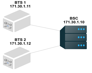
- BSC: osmo-nitb 172.30.1.10
- BTS1: osmo-bts-1 172.30.1.11
- BTS2: osmo-bts-2 172.30.1.12
BTS configuration
There are two parameters which should be set correctly in BTS configuration:
-
1.
ipa unit-id- each BTS should have unique ipa unit-id -
2.
oml remote-ip- BSC ip address
path: etc/osmocom/osmo-bts.cfg
BTS1 configuration
bts 0
 band GSM900
 ipa unit-id 1801 0
 oml remote-ip 172.30.1.10
 rtp jitter-buffer 0
 paging lifetime 0
 gsmtap-sapi bcch
 gsmtap-sapi ccch
 gsmtap-sapi rach
 gsmtap-sapi agch
 gsmtap-sapi pch
 gsmtap-sapi sdcch
 gsmtap-sapi pacch
 gsmtap-sapi pdtch
 gsmtap-sapi sacch
 fn-advance 20
 ms-power-loop -10
 timing-advance-loop
 trx 0
  rxgain 12
  power 0
 trx 1
  rxgain 12
  power 0
BTS2 configuration
bts 1
 band GSM900
 ipa unit-id 1802 0
 oml remote-ip 172.30.1.10
 rtp jitter-buffer 0
 paging lifetime 0
 gsmtap-sapi bcch
 gsmtap-sapi ccch
 gsmtap-sapi rach
 gsmtap-sapi agch
 gsmtap-sapi pch
 gsmtap-sapi sdcch
 gsmtap-sapi pacch
 gsmtap-sapi pdtch
 gsmtap-sapi sacch
 fn-advance 20
 ms-power-loop -10
 timing-advance-loop
 trx 0
  rxgain 12
  power 0
 trx 1
  rxgain 12
  power 0
BSC configuration
There are three parameters which should be checked in BSC configuration:
-
1.
ip.access unit_id- you should set the same unit id in the BSC as well as in BTS, each BTS should have unique ipa unit-id -
2.
base_station_id_code- should be unique in location area <0-63> -
3.
neighbor-list mode automatic
path: etc/osmocom/openbsc.cfg
BSC configuration
!
! OpenBSC (UNKNOWN) configuration saved from vty
!!
password foo
!
line vty
 no login
!
e1_input
 e1_line 0 driver ipa
 e1_line 0 port 0
 no e1_line 0 keepalive
network
 network country code 1
 mobile network code 1
 short name Fairwaves
 long name Fairwaves
 auth policy accept-all
 location updating reject cause 13
 encryption a5 0
 neci 1
 paging any use tch 0
 rrlp mode none
 mm info 1
 handover 1
 handover window rxlev averaging 10
 handover window rxqual averaging 1
 handover window rxlev neighbor averaging 10
 handover power budget interval 6
 handover power budget hysteresis 3
 handover maximum distance 9999
 timer t3101 10
 timer t3103 0
 timer t3105 0
 timer t3107 0
 timer t3109 4
 timer t3111 0
 timer t3113 60
 timer t3115 0
 timer t3117 0
 timer t3119 0
 timer t3122 10
 timer t3141 0
 dtx-used 0
 subscriber-keep-in-ram 0
 bts 0
  type sysmobts
  band GSM900
  cell_identity 0
  location_area_code 1
  base_station_id_code 63
  ms max power 15
  cell reselection hysteresis 4
  rxlev access min 0
  periodic location update 30
  radio-link-timeout 32
  channel allocator ascending
  rach tx integer 9
  rach max transmission 7
  channel-descrption attach 1
  channel-descrption bs-pa-mfrms 5
  channel-descrption bs-ag-blks-res 1
  ip.access unit_id 1801 0
  oml ip.access stream_id 255 line 0
  neighbor-list mode automatic
  gprs mode none
  no force-combined-si
  trx 0
   rf_locked 0
   arfcn 74
   nominal power 23
   max_power_red 0
   rsl e1 tei 0
    timeslot 0
     phys_chan_config CCCH+SDCCH4
     hopping enabled 0
    timeslot 1
     phys_chan_config SDCCH8
     hopping enabled 0
    timeslot 2
     phys_chan_config TCH/F
     hopping enabled 0
    timeslot 3
     phys_chan_config TCH/F
     hopping enabled 0
    timeslot 4
     phys_chan_config TCH/F
     hopping enabled 0
    timeslot 5
     phys_chan_config TCH/F
     hopping enabled 0
    timeslot 6
     phys_chan_config TCH/F
     hopping enabled 0
    timeslot 7
     phys_chan_config TCH/F
     hopping enabled 0
  trx 1
   rf_locked 0
   arfcn 84
   nominal power 23
   max_power_red 0
   rsl e1 tei 0
    timeslot 0
     phys_chan_config TCH/F
     hopping enabled 0
    timeslot 1
     phys_chan_config TCH/F
     hopping enabled 0
    timeslot 2
     phys_chan_config TCH/F
     hopping enabled 0
    timeslot 3
     phys_chan_config TCH/F
     hopping enabled 0
    timeslot 4
     phys_chan_config TCH/F
     hopping enabled 0
    timeslot 5
     phys_chan_config TCH/F
     hopping enabled 0
    timeslot 6
     phys_chan_config TCH/F
     hopping enabled 0
    timeslot 7
     phys_chan_config TCH/F
     hopping enabled 0
 bts 1
  type sysmobts
  band GSM900
  cell_identity 0
  location_area_code 1
  base_station_id_code 62
  ms max power 15
  cell reselection hysteresis 4
  rxlev access min 0
  periodic location update 30
  radio-link-timeout 32
  channel allocator ascending
  rach tx integer 9
  rach max transmission 7
  channel-descrption attach 1
  channel-descrption bs-pa-mfrms 5
  channel-descrption bs-ag-blks-res 1
  ip.access unit_id 1802 0
  oml ip.access stream_id 255 line 0
  neighbor-list mode automatic
  gprs mode none
  no force-combined-si
  trx 0
   rf_locked 0
   arfcn 111
   nominal power 23
   max_power_red 0
   rsl e1 tei 0
    timeslot 0
     phys_chan_config CCCH+SDCCH4
     hopping enabled 0
    timeslot 1
     phys_chan_config SDCCH8
     hopping enabled 0
    timeslot 2
     phys_chan_config TCH/F
     hopping enabled 0
    timeslot 3
     phys_chan_config TCH/F
     hopping enabled 0
    timeslot 4
     phys_chan_config TCH/F
     hopping enabled 0
    timeslot 5
     phys_chan_config TCH/F
     hopping enabled 0
    timeslot 6
     phys_chan_config TCH/F
     hopping enabled 0
    timeslot 7
     phys_chan_config TCH/F
     hopping enabled 0
  trx 1
   rf_locked 0
   arfcn 122
   nominal power 23
   max_power_red 0
   rsl e1 tei 0
    timeslot 0
     phys_chan_config TCH/F
     hopping enabled 0
    timeslot 1
     phys_chan_config TCH/F
     hopping enabled 0
    timeslot 2
     phys_chan_config TCH/F
     hopping enabled 0
    timeslot 3
     phys_chan_config TCH/F
     hopping enabled 0
    timeslot 4
     phys_chan_config TCH/F
     hopping enabled 0
    timeslot 5
     phys_chan_config TCH/F
     hopping enabled 0
    timeslot 6
     phys_chan_config TCH/F
     hopping enabled 0
    timeslot 7
     phys_chan_config TCH/F
     hopping enabled 0
2.6 Handover
Handover is the ability to keep connection an ongoing call between two base stations. You should use MultiBTS mode for osmo-nitb and osmo-bts enable handover in osmo-nitb configuration: etc/osmocom/openbsc.cfg
 handover 1
 handover window rxlev averaging 10
 handover window rxqual averaging 1
 handover window rxlev neighbor averaging 10
 handover power budget interval 6
 handover power budget hysteresis 3
 handover maximum distance 9999
NOTE:Handover configuration is available through the VTY command line. See below at 5.4 Network configuration
3. FreeSWITCH Configuration
FreeSWITCH is a scalable open source cross-platform telephony platform designed to route and interconnect popular communication protocols using audio, video, text or any other form of media. Licensed under the MPL(Mozilla Public License Version 1.0)
FreeSWITCH comes already installed and configured to route internal calls. If you would like to make external calls, you should set up the gateway for your SIP provider.
3.1 Setting up a new gateway
In order to add a new gateway you should create a new XML file in
/freeswitch/sip_profiles/external
Change directory
shell> cd /etc/freeswitch/sip_profiles/external
Create file
shell> sudo nano yourprovidername.xml
Add the following lines, inserting the proper values for your provider:
<include>
    <gateway name="yourprovidername">
        <param name="username" value="MY_USER_NAME"/>
        <param name="password" value="MY_PASSWORD"/>
        <param name="realm" value="yourprovidername.org"/>
        <param name="proxy" value="sip.yourprovidername.org"/>
    </gateway>
</include>
then you should add the configuration in the gateway.xml file
Change directory
shell>cd ../../dialplan/
Open file
shell> sudo nano gateway.xml
change the line
<action application="bridge" data="sofia/gateway/net2phone/$1"/>
on
<action application="bridge" data="sofia/gateway/yourprovidername/$1"/>
restart services
shell> sudo sv restart freeswitch
NOTE: If your system already in production you should use fs_cli for restart
Change directory
shell> cd ../../bin/
Run fs_cli
shell> ./fs_cli
Execute:
freeswitch@internal> sofia profile external restart reloadxml
NOTE: Restarting a profile will disconnect all active calls that are currently routed through that profile. An alternate command to add a newly created gateway without restarting the entire profile is:
freeswitch@internal> sofia profile <profile name> rescan reloadxml.
Exit
freeswitch@internal> /exit
3.2 FreeSWITCH Traces
In order to trace the calls:
Run fs_cli
shell> ./fs_cli
Execute:
freeswitch@internal> sofia global siptrace on
Logs show up when calls will be made.
3.3 Codecs
FreeSWITCH supports a large number of VoIP compression codecs.
type,name,ikey
codec,ADPCM (IMA),mod_spandsp
codec,AMR,mod_amr
codec,G.711 alaw,CORE_PCM_MODULE
codec,G.711 ulaw,CORE_PCM_MODULE
codec,G.722,mod_spandsp
codec,G.723.1 6.3k,mod_g723_1
codec,G.726 16k,mod_spandsp
codec,G.726 16k (AAL2),mod_spandsp
codec,G.726 24k,mod_spandsp
codec,G.726 24k (AAL2),mod_spandsp
codec,G.726 32k,mod_spandsp
codec,G.726 32k (AAL2),mod_spandsp
codec,G.726 40k,mod_spandsp
codec,G.726 40k (AAL2),mod_spandsp
codec,G.729,mod_g729
codec,GSM,mod_spandsp
codec,H.261 Video (passthru),mod_h26x
codec,H.263 Video (passthru),mod_h26x
codec,H.263+ Video (passthru),mod_h26x
codec,H.263++ Video (passthru),mod_h26x
codec,H.264 Video (passthru),mod_h26x
codec,LPC-10,mod_spandsp
codec,PROXY PASS-THROUGH,CORE_PCM_MODULE
codec,PROXY VIDEO PASS-THROUGH,CORE_PCM_MODULE
codec,Polycom(R) G722.1/G722.1C,mod_siren
codec,RAW Signed Linear (16 bit),CORE_PCM_MODULE
codec,Speex,mod_speex
codec,iLBC,mod_ilbc
More information FreeSWITCH
Change codecs
shell> nano /usr/local/freeswitch/conf/vars.xml
Find lines and set up codecs:
<X-PRE-PROCESS cmd="set" data="global_codec_prefs=G722,PCMU,PCMA,GSM"/>
<X-PRE-PROCESS cmd="set" data="outbound_codec_prefs=PCMU,PCMA,GSM"/>
4. Subscribers properties
Virtual Teletype (VTY) has the concept of nodes and commands, which consists of several words followed by a variable number of parameters. The VTY allows for runtime management and is available through telnet on the localhost. The arguments can be a single word, a string, numbers, ranges or a list of options. The available commands depend on the current node.
4.1 Virtual Teletype. Login. Privileged mode
Modifying subscriber properties requires the VTY to be in the privileged (enable) mode.
Login to VTY
shell> telnet localhost 4242
Set to privileged mode
OpenBSC# enable
4.2 Add Subscriber
A subscriber can be added to the network in 3 ways:
-
1. Inserted directly into SQL database.
-
2. Automatically, during the first connection, system automatically assigns a number, containing (IMSI, TMSI, Extension number, ID (internal identifier).
-
3. Semi- automatically from the Virtual Tele Type (VTY).
Subscribers are stored in /opt/fairwaves/api/hlr.sqlite3, which is an SQLite database file. The easiest way to add, assign, and change subscriber properties is semi-automatically through VTY.
Create the subscriber IMSI 9875648374658 OpenBSC# subscriber create imsi 9875648374658
NOTE: The "subscriber create" command assign IMSI number, ID sequences automatically. You should set up extension number and name manually.
4.3 Changing the subscriber phone number
You can set extension phone number of the subscriber with IMSI 123321123321 to 25822 by issuing the following VTY command:
OpenBSC# subscriber imsi 123321123321 extension 25822
4.4 Changing the subscriber name
In order to set subscriber name with extension number 25822 to "Chris", issue the following command:
OpenBSC# subscriber extension 25822 name Chris
NOTE: The name may contain spaces and special characters. You can verify the modified subscriber record by issuing
OpenBSC# Show subscriber extension 2522
4.5 Changing the authorization status
The HLR automatically adds records for all subscribers that are actually permitted to use the network, you can set the authorized property of the subscriber using the following VTY command: (see information above about auth policy)
OpenBSC# subscriber extension 25822 authorized 0
NOTE: If you change auth policy to closed (openbsc.cfg), handsets would fail to register but it would still create new entry in subscribers table. Set authorised to 1 to allow the handset register to your network.
OpenBSC# subscriber extension 25822 authorized 1
4.6 Changing subscriber properties
All commands are single-line commands and always start with identifying the subscriber on which the operation shall be performed. Such identification can be performed by
IMSI
International Mobile Subscriber Identity
TMSI
Temporary Mobile Subscriber Identity
Extension number
Actual number of subscriber
ID
Internal identifier
Information about a specific subscriber can be obtained from the HLR by showing the subscriber command.
For example: Display information about a subscriber with the IMSI 123321123321
OpenBSC# show subscriber imsi 123321123321
You'll see
ID: 3, Authorized: 0
Name: 'jack'
Extension: 25825
LAC: 0/0x0
IMSI: 123321123321
TMSI: 00000179
Expiration Time: Fri, 19 Dec 14 16:07:02 -0752
Pending: 0
Use count: 1
Also you can get information by extension number
OpenBSC# show subscriber extension 25825
or ID
OpenBSC# show subscriber id 1
5. Configuration via VTY
VTY can be used for files configuration. Configuration commands are available at runtime, but they are not all applied immediately. It is necessary to save the new configuration and then restart the application.
5.1 Log in
root@fairwaves:/# telnet localhost 4242
NOTE: This is the default node when connecting to the VTY interface. This node does not require any additional permission and allows to introspect the application.
Print available commands for that node
OpenBSC> list
Enable Logs
OpenBSC> logging enable
Log all messages or not
OpenBSC> logging filter all (0|1)
Set the log level for a specified category
OpenBSC> logging level (all|rll|cc|mm|rr|rsl|nm|mncc|pag|meas|sccp|msc|mgcp|ho|db|ref|gprs|ns|bssgp|llc|sndcp|nat|ctrl|smpp|lglobal|llapd|linp|lmux|lmi|lmib|lsms) (everything|debug|info|notice|error|fatal)
5.2 Privileged Node
Turn on privileged mode
OpenBSC> enable
Description of the interactive help
OpenBSC# help
Print available commands for that node
OpenBSC# list
Show running system information
OpenBSC# show network
Show system statistics
OpenBSC# show statistics
Displays program version
OpenBSC# show version
Display information about a BTS 0
(BTS number range <0-255>)
OpenBSC# show bts 0
Show running configuration
OpenBSC# show running-config
Display the session command history
OpenBSC# show history
Exit current mode and down to previous mode
OpenBSC# exit
5.3 Configuration Node
As soon as you get into VTY command promt, you will be able to change configuration
Turn on privileged mode command
OpenBSC> enable
Configuration from vty interface
OpenBSC# configure terminal
Print available commands for that node
OpenBSC(config)# list
5.4 Network Configuration
Network configuration node
OpenBSC(config)# network
Print available commands for that node
OpenBSC(config-net)# list
Set the GSM network authentication policy
OpenBSC(config-net)# auth policy accept-all
Parameters:
closed
Require the MS to be activated in HLR
accept-all
Accept all MS, whether in HLR or not
token
Use SMS-token based authentication
Set the long GSM network name
OpenBSC(config-net)# long name NAME
Set the GSM mobile network code
Code range <0-999>
OpenBSC(config-net)# mobile network code 1
Set the GSM network country code
code range <1-999>
OpenBSC(config-net)# network country code 1
Set the long GSM network name
OpenBSC(config-net)# long name NAME
Set the short GSM network name
OpenBSC(config-net)# short name NAME
Handover configuration
Enable BSC in-call handover between multiple BTS
OpenBSC(config-net)# handover (0|1)
Over how many SACCH frames should the Rx Level of the serving cell be averaged?
OpenBSC(config-net)# handover window rxlev averaging <1-10>
Over how many SACCH frames should the Rx Quality of the serving cell be averaged?
OpenBSC(config-net)# handover window rxqual averaging <1-10>
Over how many SACCH frames should the Rx Level of a neighbor cell be averaged?
OpenBSC(config-net)# handover window rxlev neighbor averaging <1-10>
Every how many SACCH frames should the BSC think about performing a power budget (rx level) handover?
OpenBSC(config-net)# handover power budget interval <1-99>
How large should the hysteresis be, i.e. to prevent continuous handover back and forth
OpenBSC(config-net)# handover power budget hysteresis <0-999>
What is the maximum distance from a BTS, after which we try to perform distance handover?
OpenBSC(config-net)# handover maximum distance <0-9999>
NOTE: For the changes to take effect you should write it into a file (see below)
Write running configuration to file (openbsc.cfg)
OpenBSC(config-net)# write file
5.5 BTS Configuration
This is the configuration of a single BTS
OpenBSC(config-net)# bts 0
Set the frequency band of this BTS (850/900/1800/1900)
OpenBSC(config-net-bts)# band 900
Write running configuration to file (openbsc.cfg)
OpenBSC(config-net-bts)# write file
More commands for that node
OpenBSC(config-net-bts)# list
5.6 TRX Configuration
This node is a sub node of the BTS node and is responsible for configuring TRX .
This is the configuration of a first transceiver
OpenBSC(config-net-bts)# trx 0
Set the ARFCN for this TRX
arfcn <0-1023>
OpenBSC(config-net-bts-trx)# arfcn 74
Real time output power control
Set power oml in etc/osmocom/osmo-bts.cfg instead of power 0 before run.
OpenBSC(config-net-bts-trx)# max_power_red 35
max_power_red parameter specifies how much dB power can be reduced
if you have 3W output power ~ 35 dBm and for the test purposes assume you may need 0.2W ~ 23 dBm, then set max_power_red = 35 - 23 = 12.
use a free tool to convert Watt to dBm
NOTE:In terms of ABIS specific, only even values allow
Write running configuration to file (openbsc.cfg)
OpenBSC(config-net-bts-trx)# write file
More VTY commands available at osmo NITB VTY
Write running configuration to file (openbsc.cfg)
OpenBSC(config-net-bts-trx)# write file
More VTY commands at osmo NITB VTY
5.7 SMPP Configuration
Use SMPP 3.4 protocol for SMS communication
SMPP configuration node
OpenBSC(config)# smpp
Print available commands for that node
OpenBSC(config-smpp)# list
Show running configuration
OpenBSC(config-smpp)# show running-config
Set the local TCP port which listen on for SMPP
OpenBSC(config-smpp)# local-tcp-port <1-65535>
Set the System ID of the SMSC
OpenBSC(config-smpp)# system-id <ID>
Set the authentication policy of the SMSC
OpenBSC(config-smpp)# policy <accept-all/closed>
accept-all - Accept all SMPP connections independeint of system ID / passwd
closed - Accept only SMPP connections from configured ESMEs
Configure a particular ESME
OpenBSC(config-smpp)# esme <NAME Alphanumeric System ID of the ESME>
Print available commands for that node
OpenBSC(config-smpp-esme)# list
Commands
route               Configure the route for MO-SMS to be send to this ESME
default-route       Set the ESME as a default-route for all SMS to unknown destinations
deliver-src-imsi    Enable the use of IMSI as source addres in DELIVER
osmocom-extensions  Enable the use of Osmocom SMPP Extensions for this ESME
dcs-transparent     Enable the transparent pass-through of TP-DCS to SMPP DataCoding
Write running configuration to file (openbsc.cfg)
OpenBSC(config-smpp-esme)# write
Example:
telnet 127.0.0.1 4242
OpenBSC> enable
OpenBSC# configure terminal
OpenBSC(config)# smpp
OpenBSC(config-smpp)#
OpenBSC(config-smpp)# local-tcp-port 2775
OpenBSC(config-smpp)# system-id OSMO-SMPP
OpenBSC(config-smpp)# esme OSMPP
OpenBSC(config-smpp-esme)# password
OpenBSC(config-smpp-esme)# password <your_pass>
OpenBSC(config-smpp-esme)# write
Configuration saved at /etc/osmocom/openbsc.cfg
6. Spectrum License Required
GSM operates in licensed frequency spectrum. As a result if you area covered by any GSM provider you should get an agreement from Regulatory authorities. You cannot operate a BTS without having obtained a license. Below the list Regulatory authorities
    Country         Name

    Austria         RTR

    Belgium         IBPT

    Germany         Bundesnetzagentur

    Netherlands     Agentschap Telecom

    Sweden          PTS

    Switzerland     Bakom

    United Kingdom  Ofcom